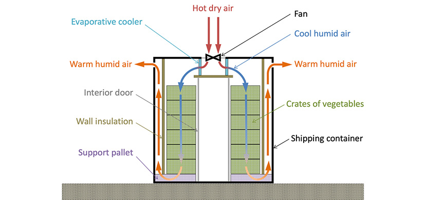
In developing countries, 30-50% of food produced is lost before it is consumed. Farmers, farmer collectives, and food vendors need an affordable cooling storage solution to increase their produce shelf life. This will not only improve profits, but also provide communities with more access to fresh produce and combat food scarcity and malnourishment. We have helped design fan and power systems of a forced-air evaporative cooling chamber that will address this issue (Figure 1). A fan system forces air through wet evaporative cooling pads, evaporating water and cooling the surrounding air that then flows into a chamber. Our solution will be housed within a 20 foot shipping container and powered by solar panels, such that it will be easily replicable in any region, regardless of access to grid power.
Activities conducted and data collected
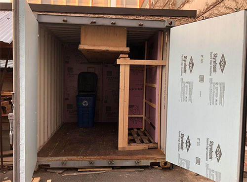
Students and staff previously set up an evaporative cooling chamber prototype and conducted experiments in the D-Lab courtyard to test and validate the system concept (Figure 2.). We analyzed this data to assess the concept effectiveness as well as the relationship between the fan/pump control systems and the chamber’s cooling capability.
To design the fan system, we measured airflow through the prototype while varying fan power, and compared these values to those estimated in a computational fluid dynamics (CFD) model. Consistent values allowed us to confidently estimate the specific fan power (SFP) of the system, which helped us select fans such that their power can meet the airflow demand of the system.
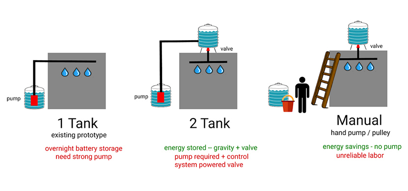
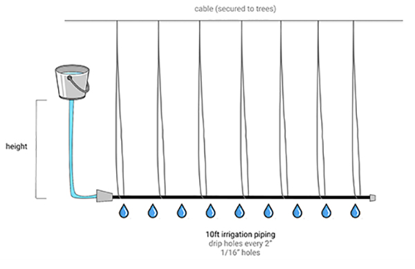
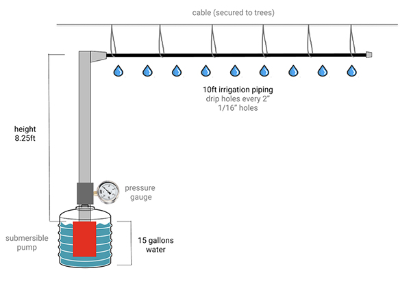
Next, we looked into the existing water system design (1 Tank design) and identified ways in which we could reduce its power consumption. We came up with two alternative designs (2 Tank and Manual) and conducted experiments to size the specifics and feasibility of the different options. The first set of experiments, shown in Figure 4, allowed us to measure the minimum flow rate necessary through the drip irrigation pipe. This ruled out the Manual design given the high volume of water that would have to flow through the system each day. This flow rate allowed us to size the water tanks for the 2 Tank design. The second set of experiments, shown in Figure 5, allowed us to measure the system head that the pump would face in either the 1 Tank or the 2 Tank designs.
The design of the power system consists of the main components, solar panels, and batteries, as well auxiliary equipment such as the charge controller and inverter. We estimated a range of energy consumption values based on the power draw of the fan and pump components. Using solar irradiance data from Global Solar Atlas, we sized the solar panels to meet this daily energy requirement. Similarly, we sized batteries to provide sufficient energy for 1.5 days of operation without exceeding a 50% depth of discharge to avoid degradation.
Next steps
At the end of the semester, both our Kenya and India partners will have a finalized fan, water, and power system design and will either have sourced or be in the process of sourcing the necessary materials to build this system. While we will not be on the ground as our community partners complete their projects, we plan to provide support and consultation from afar under Eric Verploegen’s leadership. We will also provide them with data and specs on energy and water use for the system, as well as financial models that might help inform its commercialization.
MIT D-Lab class
Applications of Energy in Global Development
Student team
MIT students unless otherwise noted.
- Alex Gerszten, G, Sloan MBA
- Stewart Isaacs, G, AeroAstro
- Alice Wu, G, EECS
- Olivia Tai, '22, Harvard College Psychology and Environmental Studies
Community partners
Hunnarshala Foundation (Gujarat, India)
- Mahavir Acharya, Managing Director
- Sandeep Virmani, Executive Vice Chairman
Solar Freeze (Kenya)
- Dysmus Kisilu, CEO (Solar Freeze)
QuestWorks (Kenya)
- Tim Kipchumba, Real Estate Developer
MIT D-Lab program
Evaporative Cooling for Vegetable Preservation Research
Contact
Eric Verploegen, MIT D-Lab Research Engineer; Evaporative Cooling Research lead; Lecturer